


The Solid State Transformer (SST) follows a modular design, with each module rated at 13.33 kW, offering scalability, ease of maintenance, and flexibility in system configuration. By electrically stacking 15 identical modules, the design aims to realise the 200 kW SST prototype, providing a clear pathway toward high-power, medium-voltage solid-state transformer systems. Each SST module comprises a Dual Active Bridge (DAB) DC–DC converter and a single-phase H-bridge inverter. When interfaced with a photovoltaic (PV) source, the DAB converter performs maximum power point tracking (MPPT) to extract the available power from the PV source, while the H-bridge inverter transfers the extracted active power to the grid and regulates the required reactive power.
To verify the functionality of the individual power-conversion stages prior to their integration, the module-level experimental test setup was built. The developed power boards, gate-driver boards, sensor boards, and digital controller boards were integrated to construct the experimental prototypes of an H-bridge inverter and a Dual Active Bridge (DAB) DC–DC converter. In addition to the main power-conversion stages, an auxiliary power supply based on a flyback converter was used to provide the low-voltage power required by the gate-driver, sensing, and controller circuits. The auxiliary supply converts the 230 V AC input supply to a regulated 24 V DC output, which is also utilised to power the associated cooling system and other auxiliary circuits.
Optical communication links were used to transmit signals between the digital controllers and the corresponding power-stage interface boards. The use of optical communication provided galvanic isolation between the control and power sections while maintaining low communication latency, thereby improving the overall safety and reliability of the experimental setup. The individual subsystems were assembled on a benchtop test platform to facilitate experimental testing and troubleshooting.
To test the DAB converter, the high-voltage DC input was supplied by a programmable DC power supply rated for up to 2.2 kV. The programmable supply was used to emulate the electrical characteristics of the DC source, such as a PV source, while providing controlled and repeatable operating conditions during experimentation. The H-bridge inverter was interfaced with the AC grid via an isolation transformer, providing galvanic isolation and enabling safe testing of the grid-connected power conversion stage.
Electrical measurements were performed using appropriate high-bandwidth measurement equipment. Differential voltage probes were used to measure the voltage across high-voltage nodes while maintaining electrical isolation from the oscilloscope inputs. High-frequency current probes were used to capture the current waveforms associated with the power-conversion stages and switching devices. The measured signals were acquired using a high-sampling-rate oscilloscope, enabling detailed observation of high-frequency switching transients, voltage and current waveforms, control responses, and other dynamic phenomena. This measurement setup facilitated accurate evaluation of the converter performance and provided valuable insight into the dynamic behaviour of the developed hardware.
This work was done by NCPRE students Sagnik, Rajvardhan, Kalyan, Navaneeth and Mithila under the guidance of Prof. Sandeep Anand.
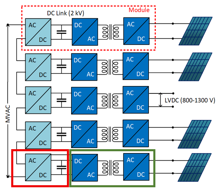
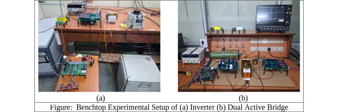
Top)Figure: The architecture of the Setup converter being(b)developed NCPRE Benchtop Experimental of (a) Inverter Dual Active at Bridge (Bottom) Benchtop Experimental Setup of Inverter (left) and Dual Active Bridge (right).