
Over the past few decades, photovoltaic (PV) power integration into the grid has grown exponentially with installations, now contributing terawatts of power. A key converter in high-power PV systems is the H-Bridge inverter, the fundamental building block of Cascaded H-Bridge (CHB) topology. As power density increases, managing heat becomes essential to ensure stable operation. A properly designed heat sink plays a vital role in dissipating the thermal energy generated by switching and conduction losses in power devices such as MOSFETs or IGBTs. The design of the heat sink starts with defining the thermal requirements based on power loss calculation in the inverter switching. Key parameters to consider are: (1) Heat source location (power device), (2) Material selection, and (3) Natural vs. forced convection. To design our heat sink we performed a Lumped Element Method (LEM) analysis. LEM models the thermal system as a series of discrete thermal resistances and capacitances, similar to an RC electrical circuit. As part of the thermal design process for the H-Bridge inverter, accurate estimation of power losses in the switching devices is critical. The heat sink was designed to dissipate power loss of 75W in H-Bridge module. By using the thermal resistance of device and thermal interface material, required thermal resistance value for Heat sink is calculated To meet the requirement, an SK481 heat sink is used, which is made up of aluminium and black anodized aluminium. To validate the design, we developed a thermal model using ANSYS. The model includes detailed geometry of the heat sink, mounting condition. Simulation results confirm maximum device temperature of 78°C under full-load conditions. This work was done by NCPRE student Kalyan under the guidance of Prof. B. G. Fernandes.
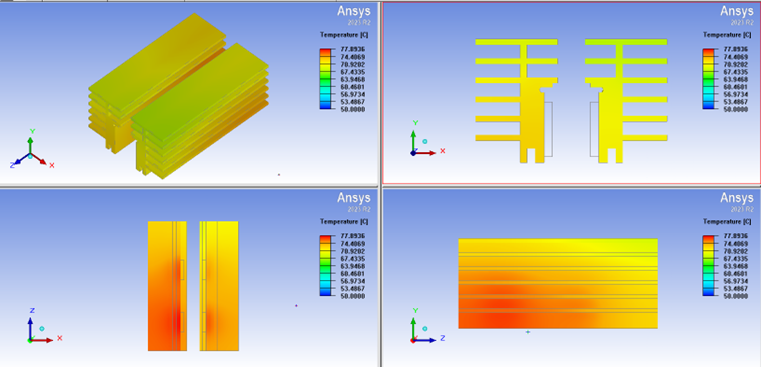
ANSYS modelling of the heat sink.